When you click on links to various merchants on this site and make a purchase, this can result in this site earning a commission. Affiliate programs and affiliations include, but are not limited to, the eBay Partner Network.
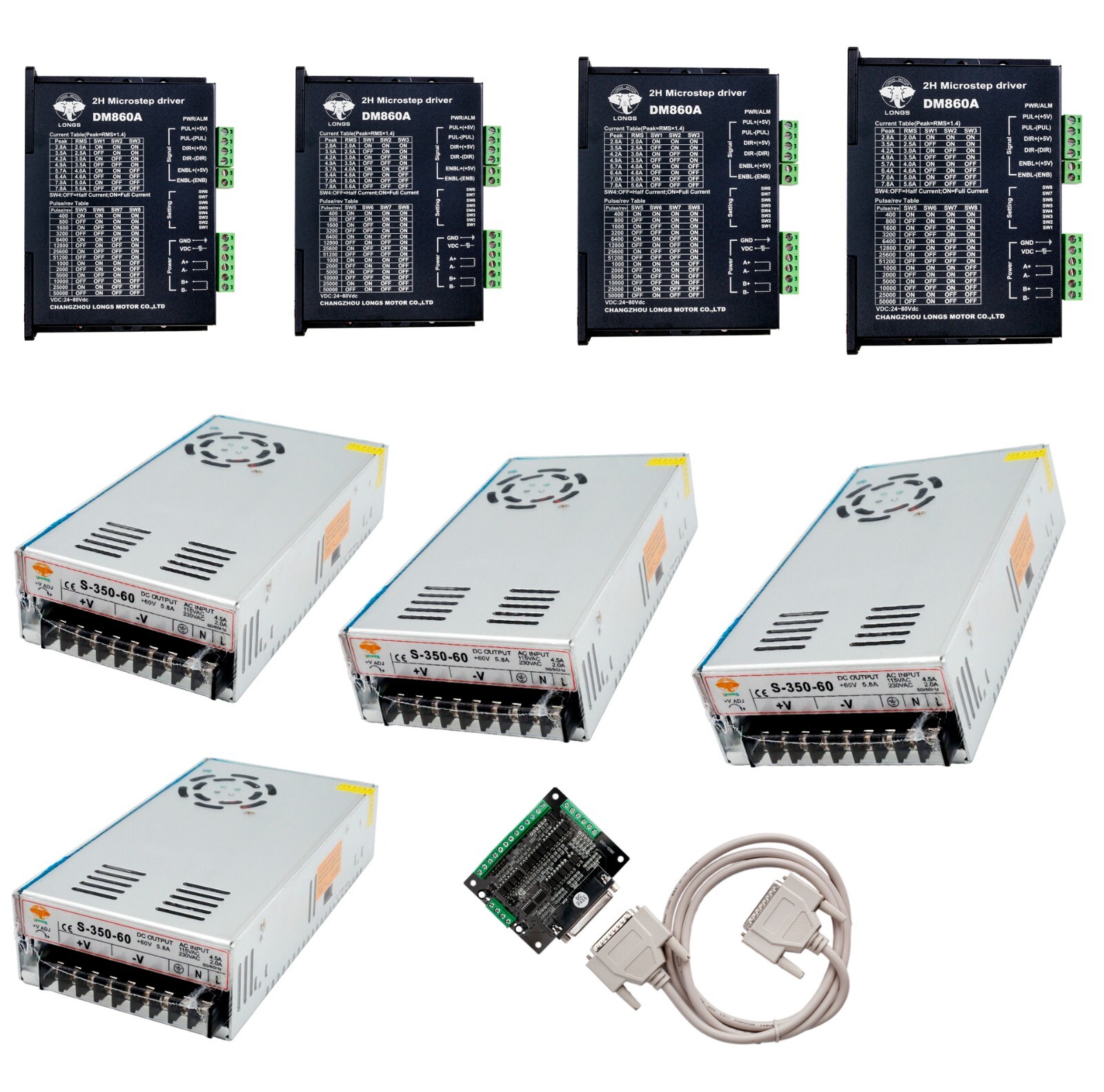
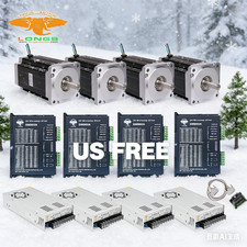
This item includes:4 pcs Steppper motor driver DM860A, peak 7.8A, 256 micsteps, 24-80VDC4 pcs Power supply 350W-60V1 pc breakout board + 1 pc parallal cable ( free offered)Detailed information
1. Stepper motor driver DM860A:
Introduction: DM860A is a type of two-phase hybrid stepping motor driver, The drive voltage of which is from 24VDC to 80VDC. It is designed for use with 2-phase hybrid stepper motor of all kinds with 57mm to 110mm outside diameter and less than 8.0A phase current. This circuit that it adopts is similar to the circuit of servo control which enables the motor run smoothly almost without noise and vibration. Hording torque when DM860A run under high speed is also significantly higher than the other two-phase driver, what’s more, the positioning accuracy is also higher. It is widely used in middle and big size numerical control devices such as curving machine, CNC machine, and computer embroider machine, packing machines and so on.Features:l High performance, low pricel Average current control, 2-phase sinusoidal output current drivel Supply voltage from 24VDC to 80VDCl Opto-isolated signal I/Ol Overvoltage, under voltage, overcorrect, phase short circuit protectionl 14 channels subdivision and automatic idle-current reductionl 8 channels output phase current settingl Offline command input terminall Motor torque is related with speed, but not related with step/revolutionl High start speedl High hording torque under high speed
Electrical specification:
Input voltage24-80VDCInput current< 6AOutput Internal Insurance:10ATemperatureWorking Temperature -10~45℃;Stocking temperature -40℃~70℃HumidityNo condensation, no water dropletsgasProhibition of combustible gases and conductive dustweight500GPins assignments and description:1)Connector PinsConfigurations
Pin Function DetailsPUL +,PUL-Pulse signal, PUL+ is the positive end of pulses input pin PUL- is the negative end of pulse input pinDIR+,DIR-DIR signal: DIR+ is the positive end of direction input pin DIR- is the negative end of direction input pinENBL+Enable signal: ENBL+ is the positive end of direction input pin. This signal is used for enabling/disabling the driver. High level for enabling the driver and low level for disabling the driver.ENBL-ENBL- is the negative end of direction input pin. Usually left unconnected (enabled)2) Pins wiring diagram:PC’s control signals can be active in high and low electrical level. When the high electrical level is active,all control negative signals will be connected together to GND. When low electrical level is active, allcontrol positive signals will be connected together to public port. Now give two examples(Open collector&PNP),please check them: Fig 1. Input port circuit (Yang connection) PC open connector output
Fig. 2 Input port circuit ( Yin connection) PC PNP outputNote: When VCC=5V, R=0 When VCC=12V, R=1K, >1/8W When VCC=24V, R=2K,>1/8WR must connect in the control signal part .3.Function choice ( Using DIP pins to achieve this function)1) Micro step resolution is set by SW 5,6,7,8 of the DIP switch as shown in the following Standstill current settingSW4 is used for this purpose. OFF meaning that the standstill current is set to be half of the selected dynamiccurrent and ON meaning that standstill is set to be the same as the selected dynamic current.3) Output current setting:The first three bits (SW 1, 2, 3)of the DIP switch are used to set the dynamic current. Select a settingClosest to your motor’s required currentOutput current Semi-flow function:Semi-flow function is that there is not step pulse after200 ms, the driver output current automaticallyreduced to 40% of rated output current, which is used to prevent motor heat.4. Pins of motor & power:Motor and power pins1A+Motors wiring2A-3B+4B-5,6DC+ DC-Power supplyPower supply :DC24-80VDCThe peak input current can not up to 6A
5. Mechanical Specification:To have 20mm of space around ,cannot be placed next to other heating devices. What’s more, avoid dust, oil mist, corrosive gas, heavy humidity and high vibration. (Unit=mm)
6. Adjustment of troubleshooting1) , the status on light’s indication
PWR: green, normal work light.
ALM: red, failure light, the motor with phase short-circuit, overvoltage and under-voltage protection.2) Troubles
Alarm indicatorReasonsMeasuresLED off turnWrong connection for powerCheck wiring of powerLow-voltages for powerEnlarge voltage of powerMotor doesn’t run, without holding torqueWrong connection of stepper motorCorrect its wiringRESET signal iseffective when offlineMake RESET ineffectiveMotor doesn’t run, butmaintainsholding torqueWithout input pulse signalAdjust PMW & signal levelMotor runs wrong directionWrong wires’ connectionChange connection for any of 2 wiresWrong input direction signalChange direction settingMotor’s holding torque is too smallToo small relative to current settingCorrect rated current settingAcceleration is too fastReduce the accelerationMotor stallsRule out mechanical failureDriver does not match with the motorChange a suitable driver
7. Driver wiringA complete stepper motor control system should contain stepper drives, DC power supply and controller (pulse source). The following is a typical system wiring diagram
2.Power Supply
350W-60V
3,Breakout board
Description:
• Built in DB25 male connector.
• DB25 Output DB25 Input Pin: P10,P11,P12,P13,P15.
• DB25 GND Pin: P18-P25.
• Power supply: +5V DC.
• Built in C-class Optical-coupler.
• High quality with Surface-mount Tech
P2 P3 is set to X-axis for the X-axis pulse
P4 P5 is set to Y-axis, Y axis pulse
P6 P7 is set to Z-axis Z-axis pulse
The other can be set to A B C axis
A-axis pulse P8 P9 is set as the A axis
P14 is set to B-axis B-axis pulse P1
P16 P17 is set to C-axis, C axis pulse
Can also be set to the spindle control signal \\ electrical permit
Input interface for the P10 P11 P12 P13 P15